DETAILED DESCRIPTION OF THE
PRESENTLY PREFERRED EMBODIMENTS
 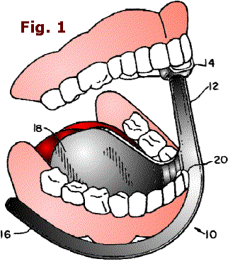 Referring now to the drawings, FIG. 1
depicts a right-sided version of an embodiment of the dental device 10 of the present invention disposed in the right side of a patient's mouth for isolating the right side of the patient's mandibular arch. Although only the right-sided version of a dental device in accordance with the present invention is discussed in detail herein, it will be appreciated that a left-sided version of the dental device 10
may also be provided. Referring now to the drawings, FIG. 1
depicts a right-sided version of an embodiment of the dental device 10 of the present invention disposed in the right side of a patient's mouth for isolating the right side of the patient's mandibular arch. Although only the right-sided version of a dental device in accordance with the present invention is discussed in detail herein, it will be appreciated that a left-sided version of the dental device 10
may also be provided.
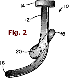 As shown in FIGS. 1-3, the dental device 10
includes a prop stem 12 for propping a patient's mouth open, an upper maxillary support 14 secured to a top section of prop stem 12 and configured to releasably support the maxillary arch of the patient, a buccal member 16 depending angularly from a bottom section of prop stem 12 for displacing the patient's cheek from the right side of the mandibular arch of the patient, and a lingual member 18 extending from a bottom section of the prop stem 12 and away from the buccal As shown in FIGS. 1-3, the dental device 10
includes a prop stem 12 for propping a patient's mouth open, an upper maxillary support 14 secured to a top section of prop stem 12 and configured to releasably support the maxillary arch of the patient, a buccal member 16 depending angularly from a bottom section of prop stem 12 for displacing the patient's cheek from the right side of the mandibular arch of the patient, and a lingual member 18 extending from a bottom section of the prop stem 12 and away from the buccal 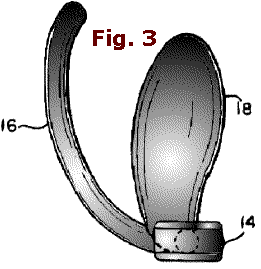 member 16 for deflecting the patient's tongue laterally from the patient's mandibular arch. The buccal and lingual members 16, 18 are spaced apart such that they are disposable on opposite sides of the patient's mandibular arch. member 16 for deflecting the patient's tongue laterally from the patient's mandibular arch. The buccal and lingual members 16, 18 are spaced apart such that they are disposable on opposite sides of the patient's mandibular arch.
Prop stem 12 is dimensioned to
span the opening of the patient's mouth such that adequate working space is provided for the dentist. Prop stem 12 has the requisite rigidity to resist bending, breaking or fracturing by typical clamping forces exerted by a patient's jaws.
Projecting from the top of the prop stem 12 is an upper maxillary support 14
for releasably securing the device 10 to the maxillary arch of the patient's mouth. The upper maxillary support 14 is preferably a generally U-shaped member so that at least a portion of the maxillary teeth may be partially confined therein for removably securing the top end of prop stem 12 to the patient's maxillary arch.
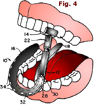 FIGS. 4 and 5 illustrate a feature of the dental device 10 comprising a mechanism for selectively varying FIGS. 4 and 5 illustrate a feature of the dental device 10 comprising a mechanism for selectively varying
the length of the
stem 12.
The adjustment mechanism may include complementary threaded portions projecting from confronting surfaces of the upper maxillary support 14 and the prop stem 12 such that relative rotation of support 14 and prop stem 12 adjusts the axial distance therebetween. For example, the prop stem 12 may include a threaded stud 21 extending from the top thereof and an internally threaded sleeve 22 depending from the bottom of the maxillary support 14. 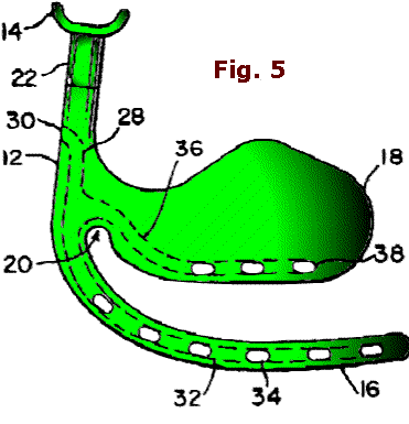 Thus, by rotating, for example, sleeve 22 in one direction or the other, support 14 is moved axially upward or downward, thereby adjusting the axial distance between support 14 and prop stem 12. Thus, by rotating, for example, sleeve 22 in one direction or the other, support 14 is moved axially upward or downward, thereby adjusting the axial distance between support 14 and prop stem 12.
FIG. 6 illustrates an alternative adjustment mechanism, wherein upper maxillary support 14 and sleeve 22 are rotatively coupled to each other so that rotation of sleeve 22 does not rotate upper support 14, thereby accommodating adjustment of the length of prop stem
12 in situ. As illustrated, the stem of a screw 40 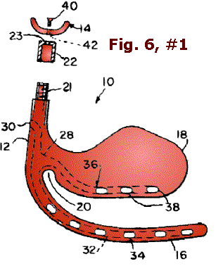 or the like extends through an opening 42 in the upper support 14
for unimpeded rotation therein, the stem being received in a blind threaded hole 23 in the top wall of sleeve 22. Thus, the rotative coupling facilitates relative rotation of the threaded sleeve 22 and the threaded stud 21 to adjust the axial distance between the upper maxillary support 14 and the prop stem 12 without relative rotation there between. or the like extends through an opening 42 in the upper support 14
for unimpeded rotation therein, the stem being received in a blind threaded hole 23 in the top wall of sleeve 22. Thus, the rotative coupling facilitates relative rotation of the threaded sleeve 22 and the threaded stud 21 to adjust the axial distance between the upper maxillary support 14 and the prop stem 12 without relative rotation there between.
Referring again to FIGS. 1-3, the buccal member 16 is preferably curved and dimensioned to follow generally an outer contour of a mandibular arch of the patient. The buccal member 16
serves to isolate the buccal side of the mandibular arch and may be flat or cylindrically shaped. To ensure adequate isolation of the buccal side of the teeth, the cross-sectional diameter of the buccal member 16 may also be dimensioned so as to deflect the patient's cheek a desired distance away from the mandibular arch. The buccal member 16 is
preferably made pliable by, for example, including a yieldable or deformable body along the length of the buccal member 16 so that the buccal member 16 may be bent or shaped to deflect the cheek of the patient from the buccal side of the teeth. It is contemplated that the yieldable body may be in the form of a properly sized wire embedded in the buccal member 16
or attached thereto.
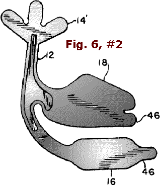
The lingual member 18 may be generally curved and plate-like in shape and configured to corral a side of the patient's tongue. The lingual member 18 serves to
isolate the lingual side of the teeth by deflecting laterally the tongue a distance from the mandibular arch. The lingual member 18 advantageously accomplishes this function without depressing the tongue or the floor of the mouth, which action could cause the patient to gag. Similar to the buccal member 16, the lingual member 18
may also be made pliable by, for example, attaching a yieldable or deformable body to the lingual member 18 or embedding the body therein.
As shown in FIGS. 4-6, dental device 10 may further include a fluid circuit comprising a plurality of apertures and conduits defined in prop stem 12
, buccal member 16 and/or lingual member 18 for aspirating fluids from the patient's mouth. For example, prop stem 12 has a side wall defining a first conduit 28 and a first aperture (e.g. outlet opening) 30 in the sidewall in fluid
communication with the first conduit 28. First aperture 30 may be threaded or otherwise configured for attachment with a vacuum tube (not shown) for drawing fluids from the fluid circuit. The buccal member 16 has a side wall defining a second conduit 32
therethrough and a plurality of second apertures (e.g. inlet openings) 34 in the side wall in communication with the second conduit 32. The lingual member 18 has a side wall defining a third conduit 36 therethrough and a plurality of third apertures (e.g. inlet openings) 38 in the side wall in communication with the third conduit 36. The first, second and third conduits 28, 32, 36 are in fluid communication for channeling the patient's fluids through a fluid circuit including the first, second and third conduits 28, 32, 36 and the first, second and third apertures 30, 34, 38.
It is contemplated that the dental device 10 may be formed as a unitary structure by way of injection molding or the like. Such a construction lowers
production costs and moreover, permits easy sterilization or disinfection for reuse since such a construction would have minimal or no crevices in which microbes can hide and breed. To accommodate different oral cavities of patients, various sizes of dental device 10 can, of course, be manufactured.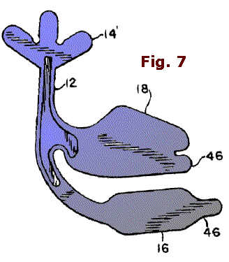 As shown in FIGS. 7 and 7A, device 10 may also be produced by a machining operation known as "stamping" wherein a predetermined pattern or shape is stamped or cut from a sheet of metal such as, for example, aluminum. Upper support 14’ in this
embodiment may be shaped as a tripod-like structure. To increase bending rigidity of stem 12 and/or neck portion 20, the cross-sec As shown in FIGS. 7 and 7A, device 10 may also be produced by a machining operation known as "stamping" wherein a predetermined pattern or shape is stamped or cut from a sheet of metal such as, for example, aluminum. Upper support 14’ in this
embodiment may be shaped as a tripod-like structure. To increase bending rigidity of stem 12 and/or neck portion 20, the cross-sec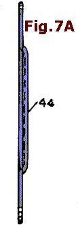 tional dimension thereof may be increased by, for example,
forming an outwardly-pushed section or embossment 44. The stamped part is subsequently configured into its functional form as depicted in FIG. 8. tional dimension thereof may be increased by, for example,
forming an outwardly-pushed section or embossment 44. The stamped part is subsequently configured into its functional form as depicted in FIG. 8.
As seen in FIGS. 7-9, the buccal and lingual members 16, 18 may include a projecting portion 46 at each of their distal ends shaped for releasable attachment with a device such as, for example, a suction tube 48 having a plurality of apertures 49 along its longitudinal axis for aspirating fluids from the patient's mouth. The suction tube 48 may include a ring-like structure 50 having an annular opening 52 that is sized for frictional receipt of the projecting portion 46 for releasably attaching the suction tube 48 to the buccal and/or lingual members 16, 18.
In use, a dentist may removably secure, for example, a
left-sided version of the dental device 10 in a patient's mouth by positioning the buccal and lingual members 16, 18 along the buccal and 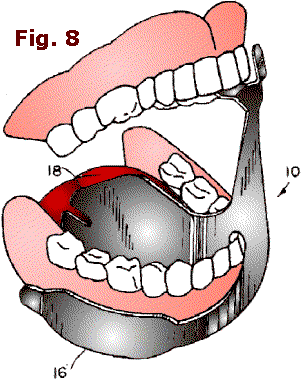 lingual sides of the patient's mandibular arch, resting the
neck portion 20 of the lingual member 18 on the patient's mandibular teeth and manipulating the upper support 14 to receive the patient's upper maxillary teeth as the patient closes his mouth. The device 10 is thereby releasably secured to the patient's mouth. If the dental device has pliable
buccal and lingual members 16, 18, the dentist may precisely shape, orient or conform these members to fit the particular contours of the patient. If the embodiment of dental device 10 provides conduits 28, 32, 36
therewithin, the user may attach a vacuum tube to the outlet opening 30 in the prop stem 12 for aspirating fluids from the patient's mouth. lingual sides of the patient's mandibular arch, resting the
neck portion 20 of the lingual member 18 on the patient's mandibular teeth and manipulating the upper support 14 to receive the patient's upper maxillary teeth as the patient closes his mouth. The device 10 is thereby releasably secured to the patient's mouth. If the dental device has pliable
buccal and lingual members 16, 18, the dentist may precisely shape, orient or conform these members to fit the particular contours of the patient. If the embodiment of dental device 10 provides conduits 28, 32, 36
therewithin, the user may attach a vacuum tube to the outlet opening 30 in the prop stem 12 for aspirating fluids from the patient's mouth. 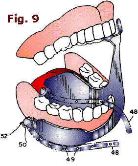
In accordance with another embodiment of the present
invention and as shown in FIG. 10, the dental device 60 also includes buccal and lingual members 16, 18, but instead of or in addition to prop stem 12, device 60 has an elongated chin bar 62 extending downwardly from the lingual and buccal
members 16, 18 for releasably securing device 60 to the patient's lower jaw. The chin bar 62 has a bottom section 64 configured to corral or grip the patient's chin. The chin bar 62 is preferably made pliable as was described above so that it can be selectively shaped to a patient's lower jaw.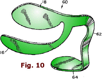
Again, as in the embodiments of FIGS. 4-6, the dental device 60 depicted in FIG. 13
may further include a fluid circuit comprising a plurality of apertures and conduits defined in the chin bar 62, the buccal member 16 and/or the lingual member 18 for aspirating fluids from the patient's mouth. In this embodiment, the chin bar 62 has a side wall defining a first conduit 66 and a first aperture (e.g. outlet opening) 68 in the sidewall in fluid communication with the first conduit 66.  First aperture 68 may be threaded for
attachment with a vacuum tube (not shown). The lingual member 18 has a side wall defining a second conduit 70 therethrough and a plurality of second apertures (e.g. inlet openings) 72 in the side wall in communication with second conduit 70. The buccal member 16
has a side wall defining a third conduit 74 therethrough and a plurality of third apertures (e.g. inlet openings) First aperture 68 may be threaded for
attachment with a vacuum tube (not shown). The lingual member 18 has a side wall defining a second conduit 70 therethrough and a plurality of second apertures (e.g. inlet openings) 72 in the side wall in communication with second conduit 70. The buccal member 16
has a side wall defining a third conduit 74 therethrough and a plurality of third apertures (e.g. inlet openings)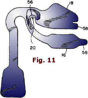 76 in the side wall in communication with the third conduit 74. The first, second and third conduits 66, 70, 74 are in fluid communication for channeling the patient's fluids through the fluid circuit comprising the first, second and third conduits 66, 70, 74 and the first, second and third apertures 68, 72, 76. 76 in the side wall in communication with the third conduit 74. The first, second and third conduits 66, 70, 74 are in fluid communication for channeling the patient's fluids through the fluid circuit comprising the first, second and third conduits 66, 70, 74 and the first, second and third apertures 68, 72, 76.
Dental device 60 may also be formed as a unitary structure by way of injection molding or the like. To accommodate individual patients, various sizes of device 60
can also be produced. As shown in FIGS. 11 and 11A, device 10 may be produced by stamping wherein a predetermined shape is cut from a sheet of metal such as, for example, aluminum. To increase bending rigidity of the neck portion 20, the cross-sectional size of the chin bar 62 may be increased by, for example, forming an outwardly-deformed section or embossment 56 therein. The stamped part may be shaped into its functional form as depicted in FIG. 12. 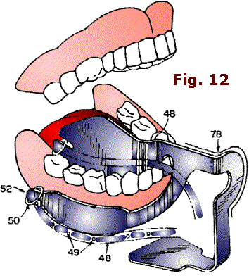
Similar to the embodiment shown in FIG. 9, the buccal and lingual members 16, 18 of device 60 may also include a projecting portion 58 at each of their distal ends (as illustrated in FIG. 12). The projecting portion 58 is shaped for releasable attachment with a device such as, for example, suction tube 48 for aspirating fluids from the patient's mouth. The suction tube 48 may include a ring-like structure 50 connected to an end of the tube.
The ring-like structure 50 has an annular opening 52 that is sized for frictional engagement of the projecting portion 58 for releasably attaching the suction tube 48 to the buccal and/or lingual members 16, 18.
As shown in FIG. 12, the device 10 and/or ring-like structure 50 may further include a resilient layer 78 such as, for example, silicone or the like disposed or otherwise attached to an outer surface of device 10 or ring-like structure 50 for increasing the level of comfort to the patient as well as for protecting oral tissues from injury.
In use, the buccal and lingual members 16, 18 of device 60 may be placed in the patient's mouth as was described for device 10. But instead of relying on a
prop stem and a maxillary support for releasable attachment with the patient's mouth, device 60 utilizes the chin bar 62 to anchor the device to the patient's lower jaw by conforming or gripping bottom section 64 to the underside of the patient's chin. Thus disposed, bottom section 64 of chin bar 62 imparts a slight clamping force to the patient's chin while neck portion 20 of chin bar 62 imparts an opposing clamping force onto the patient's mandibular teeth. If the particular embodiment provides for a pliable chin bar, the dentist may precisely conform the chin bar 62 to the specific contour of the patient's chin for improved
anchoring.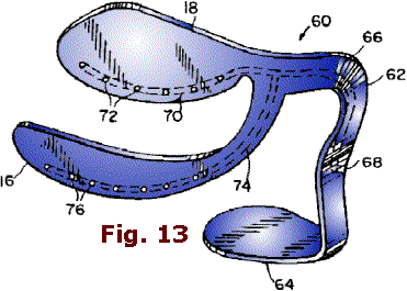
Thus, while there have been shown and described and pointed out fundamental novel features of the invention as applied to a preferred embodiment thereof, it will be understood that various omissions and substitutions and changes in the form and details of the devices illustrated, and
in their operation, may be made by those skilled in the art without departing from the spirit of the invention. For example, it is expressly intended that all combinations of those elements and/or method steps which perform substantially the same function in substantially the same way to achieve the same results are within the scope of the invention. Moreover, it should be recognized that structures and/or elements and/or method steps shown and/or
described in connection with any disclosed form or embodiment of the invention may be incorporated in any other disclosed or described or suggested form or embodiment as a general matter of design choice. It is the intention, therefore, to be limited only as indicated by the scope of the claims appended hereto.
 |